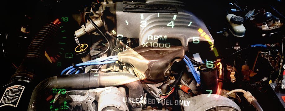
The fox Mustang’s EEC IV computer has two connectors for self-testing and located on the driver-side firewall. The large connector contains the self test output (STO) and ground (SIG RTN). The small pigtail is the self test input (STI). You can easily grab your trouble codes, and this will help you diagnose your MIL or “Check engine ” light on that fox body Mustang of yours! Note: Make sure your engine is warmed up before doing these tests.
Counting Digits to Get Your Trouble Codes
If you don’t have a code-scanner, you can count the signals and find the codes that way. It may take patience to do so but doable. To get a code digit: There’s a 2 second pause between digits and 4 second pause between codes. So for code example “21”, you will count two flashes, a 2 second pause, then a single flash, if there’s another code – it will pause 4 seconds.
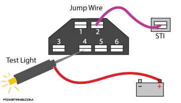
Using a Test Light (86-88 Mustangs)
The 86 to 88 Mustangs will need a jumper wire from the STI (test input) with the #2 pin on the connector (I’d use spades) and you can hook your light to #4 on the connector and (+) to the positive battery terminal.
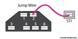
Using The Check-Engine Light (89-93 Mustangs)
The 89-93 Mustangs (and the 94-95’s as well as some ’88 MAF equipped Mustangs) will allow you to use a jump wire and count the check-engine light in the dash. The jump wire (I’d use spades on each end) would connect the STI (test input) with #2 pin on the connector, see below:
Test Conditions and EEC-IV Codes Below:
(O) =Key On Engine Off (KOEO)
(R) =Key On Engine Running (KOER)
(M) =Memory code
(C) = Continuous memory
2 Digit Codes
| Code | Condition | Cause |
|---|---|---|
| 11 | O,R,C | System OK, testing complete |
| 12 | R | Idle speed control out of specified range |
| 13 | O,R,C | Normal idle not within specified range |
| 14 | O,C | Ignition profile pickup erratic |
| 15 | O | ROM test failure |
| 15 | C | Power interrupt to computer memory |
| 16 | R | Erratic idle, oxygen sensor out of range or throttle not closing |
| 17 | R | Curb idle out of specified range |
| 18 | R | SPOUT circuit open |
| 19 | O | No power to processor |
| 19 | R | Erratic idle speed or signal |
| 21 | O,R | Coolant temperature out of specified range |
| 21 | O,R,C | Coolant temperature sensor out of specified range |
| 22 | O,R,C | MAP sensor out of specified range |
| 23 | O,R,C | Throttle position signal out of specified range |
| 24 | O,R | Air charge temperature low |
| 25 | O,R | Mass Air Flow sensor or circuit |
| 27 | C | Vehicle Speed Sensor or circuit |
| 28 | 0,R | Vane air temperature sensor or circuit |
| 29 | C | No continuity In Vehicle Speed Sensor circuit |
| 31 | O,R,C | Canister or EGR valve control system |
| 32 | O,R,C | Canister or EGR valve control system |
| 33 | R,C | Canister or EGR valve not operating properly |
| 34 | O,R,C | EVP voltage above closed unit |
| 35 | O,R,C | EGR pressure feedback, regulator circuit |
| 38 | C | Idle control circuit |
| 39 | C | Automatic overdrive circuit |
| 41 | C | Oxygen sensor signal |
| 41 | R | Lean fuel mixture |
| 42 | R,C | Fuel mixture rich |
| 43 | C | Lean fuel mixture at wide open throttle – |
| 43 | R | Engine too warm for test |
| 44 | R | Air management system inoperative |
| 45 | R | Thermactor air diverler circuit |
| 46 | R | Thermactor air bypass circuit |
| 47 | R | Low flow of unmetered air at idle |
| 48 | R | High flow of unmetered air at idle |
| 49 | C | SPOUT signal defaulted to 1 0-degrees |
| 51 | O,C | Coolant temperature sensor out of specified range |
| 52 | O,R | Power steering pressure switch out of specified range |
| 53 | O,C | Throttle Position Sensor input out of specified range |
| 54 | O,C | Vane air flow sensor or air charge temperature sensor |
| 55 | R | Charging system under specified voltage (1984 through 1988) |
| 55 | R | Open ignition key power circuit (1984 through 1988) |
| 56 | O,R,C | Mass Air Flow sensor or circuit |
| 57 | C | Transmission neutral pressure switch circuit |
| 58 | O | CFI – idle control circuit; EFI – vane air flow circuit |
| 58 | R | Idle speed control motor or circuit |
| 58 | C | Vane air temperature sensor or circuit |
| 59 | O,C | Transmission throttle pressure switch circuit |
| 61 | O,C | Coolant temperature switch out of specified range |
| 62 | 0 | Transmission circuit fault |
| 63 | O,C | Throttle Position Sensor or circuit |
| 64 | O,C | Air Charge Temperature (ACT) sensor |
| 65 | C | Fuel control system not switching to closed loop |
| 66 | O,C | No Mass Air Flow sensor signal |
| 67 | O,R,C | Neutral drive switch or circuit |
| 67 | C | Air conditioner clutch switch circuit |
| 69 | O,C | Vehicle Speed Sensor or circuit |
| 72 | C | System power circuit, electrical interference |
| 72 | R | No Manifold Absolute Pressure or Mass Air Flow sensor signal fluctuation |
| 73 | O,R | Throttle Position Sensor or circuit 21 |
| 74 | R | Brake on/off ground circuit fault 21 |
| 75 | R | Brake on/off power circuit fault 22 |
| 76 | R | No vane airflow change |
| 77 | R | Throttle “goose” test not performed |
| 78 | C | Power circuit 1 |
| 79 | O | Air conditioner clutch circuit |
| 81 | O | Thermactor air circuit |
| 82 | O | Thermactor air circuit, integrated controller circuit |
| 83 | O | EGR control circuit (four-cylinder models oeM |
| 83 | O | Cooling fan circuit (V6 models only) |
| 83 | O,C | Low speed fuel pump relay (1984 through 1988 models) |
| 83 | O,C | EGR solenoid or circuit (1989 and later models) |
| 84 | O,R | EGR control circuit |
| 85 | O,R | Canister purge circuit or transmission shift control circuit |
| 85 | C | Excessive fuel pressure or flow |
| 85 | C | Canister purge circuit |
| 86 | C | Low fuel pressure or flow |
| 87 | O,R,C | Fuel pump circuit D2 |
| 88 | O | Integrated controller |
| 89 | O | Lock-up solenoid |
| 91 | R,C | Oxygen sensor problem, fuel pressure out of specified range or injectors out of balance |
| 92 | R | Fuel mixture rich, fuel pressure high |
| 93 | O | Throttle Position Sensor or circuit D |
| 94 | R | Secondary air system inoperative |
| 95 | O,C | Fuel pump circuit problem |
| 95 | R | Thermactor air diverter circuit |
| 96 | O,C | Fuel pump circuit |
| 96 | R | Thermactor air bypass circuit |
| 98 | R | Repeat test sequence |
| 99 | R | Repeat test sequence |
| 99 | R | System has not learned to control idle speed |
3 Digit Codes (some 91+)
| Code | Condition | Cause |
|---|---|---|
| 111 | O,R,C | System Pass |
| 112 | O,R,C | Air Charge Temp (Ad) Sensor circuit below minimum voLtagE/ 254 F |
| 113 | O,C | Air Charge Temp (ACT) Sensor circuit above maximum voltagE/ -40 F |
| 114 | O,R | Air Charge Temp (ACT) out of self test range |
| 116 | O,R | Coolant Temp (ECT) out of self test range |
| 117 | O,R | Coolant Temp (EdT) Sensor circuit below minimum voltage/ 254 F |
| 118 | O,C | Coolant Temp (EdT) Sensor circuit above maximum voitage/ -40 F |
| 121 | O,C | Closed Throttle Voitage higher or lower than expected |
| 122 | O,R,C | Throttle Position (TP) Sensor circuit below minimum voltage |
| 123 | O,C | Throttle Position (TP) Sensor circuit above maximum voltage |
| 124 | O,C | Throttle Position (TP) Sensor voltage higher than expected |
| 125 | C | Throttle Position fTP) Sensor voltage lower than expected |
| 126 | C | BP Sensor higher or lower than expected |
| 129 | O,R,C | Insufficient Mass Air Flow (MAE) change during Dynamic Response Test |
| 144 | C | No Oxygen Sensor (HEGO) Switches detected |
| 157 | C | Mass Air Flow (MAE) Sensor circuit below minimum voltage |
| 158 | O,C | Mass Air Flow (MAE) Sensor circuit above maximum voltage |
| 159 | O,R | Mass Air Flow (MAE) Sensor out of self test range |
| 167 | R | Insufficient Throttle Position change during Dynamic Response Test |
| 171 | C | Fuel system at adaptive limits, Oxygen Sensor (HEGO) unable to switch |
| 172 | R,C | Lack of Oxygen Sensor (HEGO) Switches, indicates lean |
| 173 | R,C | Lack of Oxygen Sensor (HEGO) Switches, indicates rich |
| 179 | C | Fuel system at lean adaptive limit at part throttle, system rich |
| 181 | C | Fuel system at rich adaptive limit at part throttle, system lean |
| 182 | C | Fuel system at lean adaptive limit at idle, system rich |
| 183 | C | Fuel system at flch adaptive limit at idle, system lean |
| 184 | C | Mass Air Flow (MAE) higher than expectec |
| 185 | C | Mass Air Flow (MAE) lower than expected |
| 186 | C | Injector pulse width higher than expected |
| 187 | C | Injector pulse width lower than expected |
| 211 | C | Profile Ignition Pickup (PIP) circuit fault |
| 212 | C | Ignition module circuit failure – SPOUT circuit grounded |
| 213 | R | SPOUT circuit |
| 214 | C | Cylinder Identification (CID) circuit failure |
| 215 | C | EEC Processor detected Coil 1 primary circuit failure |
| 216 | C | EEC Processor detected Coil 2 primary circuit failure |
| 218 | C | Loss of ignition Diagnostic Monitor (1DM) signal-left side |
| 222 | C | Loss of Ignition Diagnostic Monitor (1DM) signal-right side |
| 223 | C | Loss of Dual Plug Inhibit (DPI) control |
| 224 | C | Erratic Ignition Diagnostic Monitor (1DM) input to processor |
| 225 | R | Knock riot sensed during Dynamic Response Test |
| 327 | O,R,C | EVP circuit below minimum voltage |
| 328 | O,R,C | EGR “closed valve” voltage lower than expected |
| 332 | R,C | Insufflcjent EGR flow detected |
| 334 | O,R,C | EGR closed valve voltage higher than expected |
| 337 | O,R,C | EVP circuit above maximum voltage |
| 341 | O | Octane Adjust Service Pin in use |
| 411 | R | Cannot control RPM during KOER low rpm check |
| 412 | R | Cannot control rpm during KOER high rpm check |
| 452 | C | Isufflcient input from Vehicle Speed Sensor (VSS) |
| 511 | O | EEC Processor Read Only Memory (ROM) test failure |
| 512 | C | EEC Processor Keep 4Jive Memory (KAM) test failure |
| 519 | O | Power Steering Pressure Switch (PSPS) circuit open |
| 521 | R | Power Steering Pressure Switch (PSPS) circuit did not change states |
| 522 | O | Vehicle not in PARK or NEUTRAL during KOEO |
| 528 | C | Clutch Switch Circuit failure |
| 536 | R,C | Brake On/Off (BOO) circuit failure I not actuated during KOER |
| 538 | R | IsuffIcient RPM change during KOER Dynamic Response Test |
| 539 | O | AC On/Defrost ON during KOEO |
| 542 | O,C | Fuel Pump secondary circuit failure |
| 543 | O,C | Fuel Pump secondary circuit failure |
| 556 | O,C | Fuel Pump Relay primary circuit failure |
| 558 | O | EGR Vacuum Regulator (EVR) circuit failure |
| 564 | 0 | ElectrOD FAN( EDF) circuit failure |
| 565 | O | Canister Purge (CANP) circuit failure |
| 566 | O | 3-4 Shift Solenoid circuit failure |
| 629 | O | Converter Clutch Control circuit failure |
| 998 | O,R | Hard Fault present |